Smart Linear Position Sensing Cylinder CYLNUC,NSD Group Vietnam,Xylanh cảm biến vị trí NSD VIET NAM,CSA-20×250-FA7-C2.0-A1
Hãng sản xuất: NSD Group
Description

CYLNUC is NSD smart linear position sensing cylinder that indicates the amount of linear travel and rod extension throughout the range of sensing stroke.
Model coding
CSA-[a]×[b]-[c][d]-C[e]-[f]
Standard model code:CSA-20×250-FA7-C2.0-A1
| Item | Code | Description | |||
|---|---|---|---|---|---|
| a | Bore size | 20 | Φ20 | Units : mm | |
| 40 | Φ40 | ||||
| b | Stroke length | 30 ~ 500 | Φ20 | Standard stroke : 50, 100, 150, 200, 250, 300, 350, 400, 450, 500 | Units : mm |
| 30 ~ 700 | Φ40 | Standard stroke : 50, 100, 150, 200, 250, 300, 350, 400, 450, 500, 600, 700 | |||
| c | Mounting style | [FA]Flange on rod end side |
|||
[LS]Foot on rod end side /parallel to axis  |
|||||
[TB]Trunnion on head end side |
|||||
[FB]Flange on head end side |
|||||
[LB]Foot both ends /parallel to axis  |
|||||
| d | Max. operating pressure | 7 | 0.7 MPa | ||
| 0 | Piston with hole | ||||
| e | nterconnecting sensor cable length | 2.0 | 2 m | ||
f |
Option | A1 | Lock nut (accessory) | ||
| A2 | Clevis / single | ||||
| A3 | Clevis / double (supplied with a Pivot pin A4) | ||||
| A4 | Pivot pin (for Clevis) | ||||
| C4 | Bellows | ||||
Contact us about other specifications.
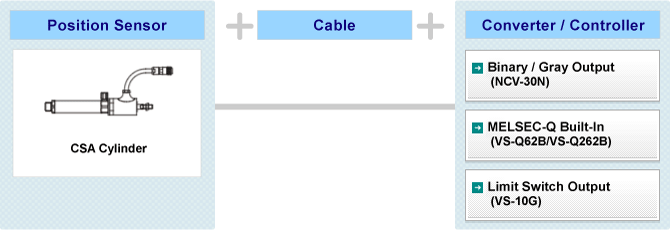
System Configuration
Specification
Cylinder
| Item | Specification | ||
|---|---|---|---|
| Bore size | Φ20 | Φ40 | |
| Rod diameter(mm) | Φ10 | Φ14 | |
| Stroke(mm) | Without bellows | 30 ~ 500 | 30 ~ 700 |
| With bellows | |||
| Operating pressure range(MPa) | 0.1 ~ 0.7 | ||
| Proof pressure(MPa) | 1.05 | ||
| Operating fluid | Compressed air | ||
| Cylinder speed range(mm/s) | 50 ~ 500 | ||
| Ambient operating temperature(℃) | 5 ~ 60 | ||
Applicable sensor
|
|---|
Theoretical cylinder thrust values at various operating pressures
| Bore size (mm) |
Cross-sec. area of cylinder (mm2) |
Rod dia. (mm) |
Cross-sec. area of piston rod (mm2) |
Area of piston's rod face (mm2) |
Cylinder thrust (N) | ||||||
|---|---|---|---|---|---|---|---|---|---|---|---|
| 0.2MPa | 0.3MPa | 0.4MPa | 0.5MPa | 0.6MPa | 0.7MPa | ||||||
| Φ20 | 314 | Φ10 | 78 | Push | 314 | 62 | 94 | 125 | 157 | 188 | 219 |
| Pull | 235 | 47 | 70 | 94 | 117 | 141 | 164 | ||||
| Φ40 | 1256 | Φ14 | 153 | Push | 1256 | 251 | 376 | 502 | 628 | 753 | 879 |
| Pull | 1102 | 220 | 330 | 441 | 551 | 661 | 771 | ||||
Mass
| Bore size (mm) |
Basic mass (ZERO stroke) (kg) |
Stroke mass per 10 mm (kg) |
Additional mass depending on mounting format (kg) | ||||
|---|---|---|---|---|---|---|---|
| FA | FB | LB | LS | TB | |||
| Φ20 | 1.2 | 0.01 | 0.06 | 0.06 | 0.15 | 0.08 | 0.10 |
| Φ40 | 1.5 | 0.02 | 0.15 | 0.15 | 0.26 | 0.13 | 0.20 |


 Mr. Tú


