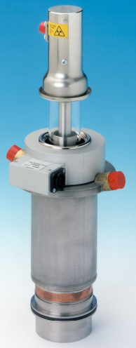
MG6028 Magnetron, E2V Vietnam , MG6028 E2V, E2V magnetron MG6370E
Hãng sản xuất: Other Brands
MG6028 Magnetron, E2V Vietnam , MG6028 E2V, E2V magnetron MG6370E, Máy phổ xung phát xạ Magnetron MG6370E E2V Vietnam, Đại lý E2V Việt Nam
1. The ideal supply would be an amplifier that can be driven positive or negative by a DC input signal. 2. The frequency range 2856 to 2859 MHz is achieved at all conditions. The frequency at any tuner setting will increase by 630 kHz per kW reduction in mean input power. For other conditions, contact e2v technologies. 3. The magnetron must be protected from the load by an isolator or circulator. The maximum VSWR at 2856 MHz is 1.3:1 and must not exceed 2:1 over the range 2800 to 3500 MHz. 4. With no anode input power. Prior to the application of anode voltage, the cathode must be heated to the required initial temperature by the application of 13 V to the heater for at least six minutes. Within 30 seconds after the application of anode voltage the heater must be reduced as follows: Mean input power Heater voltage (kW) (V) 0 - 2 12.0 2 - 4 10.0 4 - 6 8.0 6 - 7 6.0 The heater voltage must be maintained within 5% of the specified value. A rectified supply is recommended for operating the magnetron. The use of any AC supply may cause frequency modulation. e2v technologies should be consulted if the magnetron is to be operated with any supply other than DC. A coaxial lead must be used to connect the magnetron to the filament transformer or pulse transformer, the outer being the cathode pulse connection. Capacitors must be used to prevent pulse voltages being applied to the heater, either from unbalance of a bifilar pulse transformer or by induction from the pulse current; this protection must be effective both for normal operation and in the event of the magnetron sparking. Capacitors up to 10 F may be required, shunted by small high frequency capacitors. 5. A positive current results in a frequency increase. 6. The coil will overheat without the specified cooling through the water jacket. 7. The minimum air pressure in the output waveguide can vary with the peak power level at which the magnetron is operated. It should not be less than 172 kPa at 1 MW, 241 kPa at 3 MW and 310 kPa at 5 MW. At the maximum pressure of 448 kPa the leakage will not exceed 0.03 litre (NTP) per minute. The output waveguide may also be filled with an arc suppressant gas, such as SF6 to a minimum static gauge pressure of 28 kPa. When using such a gas, it is mandatory that the waveguide be emptied and refilled with new arc suppressant gas at regular intervals to avoid possible dilution or contamination. The interval should not exceed 2 months or 100 hours of high voltage application, whichever is reached first. The gas should also be replaced immediately if arcing in the output waveguide is suspected, as such arcing may cause loss of stability in the magnetron. 8. Measured at the point indicated on the electromagnet outline drawing; the axial distribution must be that produced by the MG6030 electromagnet or authorised equivalent. 9. The modulator must have an efficient overswing damping system, such that the pulse energy delivered to the magnetron following an arcing pulse does not appreciably exceed the normal pulse energy. An interlock relay must be used to trip the modulator in the event of excessive magnetron arcing, preferably operated by the overswing diode current. The trip should operate if the magnetron arcs for 25 consecutive pulses. Positive overswing at the end of the voltage pulse should be less than 10% of drive voltage. 10. The various parameters are related by the formula: Pi = iapk x Vapk x Du where Pi = mean input power in watts iapk = peak anode current in amperes vapk = peak anode voltage in volts and Du = duty cycle 11. The rate of rise of voltage is defined as the steepest tangent to the leading edge of the voltage pulse above 80% amplitude. 12. Tolerance 10%. 13. The load termination of the magnetron during this test is a waveguide with a VSWR of less than 1.1:1 at the oscillation frequency and less than 1.5:1 between 3200 and 3500 MHz. 14. The magnetron tuning range includes the two limits given. 15. Pulses are defined as missing when the RF energy level is less than 70% of the normal energy level in the frequency range 2852 to 2861 MHz. Missing pulses are expressed as a percentage of the number of input pulses applied during any 5 minute interval of a 10 minute test period. 16. Measured with a VSWR of 1.3:1 at the frequency of oscillation, varied through all phases. 17. Measured with a heater voltage of 13 V and no anode input power, the heater current limits are 13 A minimum, 15 A maximum. 18. Design test only. The maximum frequency change with anode temperature change (after warming) is 0.05 MHz/C. 19. The heater will be operated at 8 V for the duration of the life test and for subsequent specification tests. 20. If the mean output power falls below 2500 W, the duty cycle may be reduced to 0.0005.


 Mr. Tú